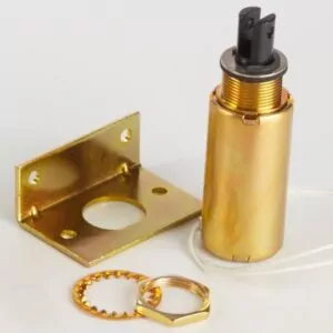
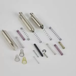
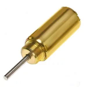
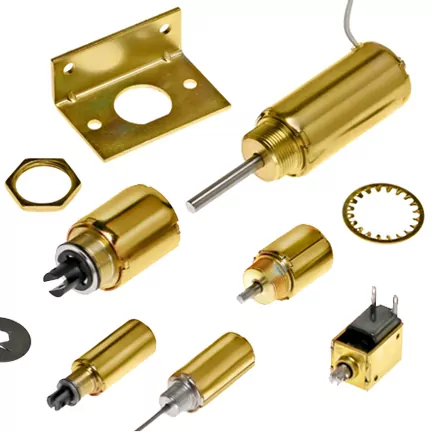
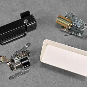
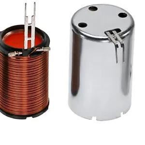
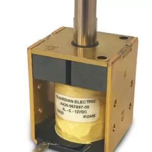
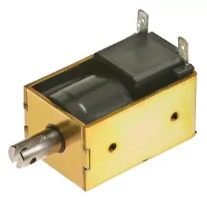
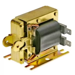
AC & DC SOLENOID SELECTION FACTORS
A linear solenoid is an electromechanical device which converts electrical energy into linear mechanical motion. This motion is used to move an external load a specified distance.
When electrical power is applied, the solenoids plunger and its external load accelerates and moves toward the solenoid’s stop until an impact occurs. When power is removed, the plunger and external load returns to the rest position aided by a return spring, gravity or the load itself.
The following factors must be considered in selecting a solenoid to perform the required work satisfactorily and reliably over an extended period of time.
- Force
- Stroke
- Duty Cycle
- Temperature
Other considerations are:
- Size
- Mounting
- Electrical Connections
- Life Expectancy
- Environment
DC PLUG AND PLUNGER CONFIGURATIONS
The curves shown here give a general idea of the differences in force stroke relationship among four basic plug and plunger geometries; flat face, 60 degree conical, 90 degree conical and stepped conical. The flat faced configuration is best for short strokes and high holding force, whereas the 60 degree conical is best for longer strokes. The 90 degree conical and stepped conical are better for medium strokes.
Guardian’s standard is the 60 degree conical, but any of the others shown, are available for custom application. Configurations other than the above can be tailored to meet some unusual force/stroke requirements. Consult the factory for specific details.
DC WORK REQUIREMENTS VS. SOLENOID CAPABILITIES
The force developed by a DC solenoid at a given stroke is proportional to the product of the number of turns (N) in the coil winding and the current (I) flowing through those turns; commonly referred to as ampere-turns or NI. The NI produced by a DC solenoid is affected by two major variables:
- Manufacturing Tolerances
- Coil Temperature
The manufacturing variations are in the total number of turns and coil resistance. Normal manufacturing variations on other parts have no effect on the NI produced. Since coil resistance and therefore coil current and NI are affected by temperature, the force developed is also affected. To determine the force developed, the total coil temperature due to both ambient temperature and self heating, must be taken into consideration.
Normal production will yield the majority of units within 5% of the nominal. However, the user must anticipate that some units will be above and below that 5%.
The solenoid selected for a particular application must be one which produces the force required throughout its entire stroke, and operating temperature range. If the load is too great, the plunger will not pull in or seat. On the other hand, a highly over-rated solenoid which develops substantially more force than required by the load should not be used unless speed of operation is the determining factor. Excessive energy imparted to the solenoid must be dissipated by some other means. If it is not dissipated, the plunger and field piece assembly must absorb the energy of impact causing premature failure. As coil temperature increases, force developed decreases. The variation in force due to temperature cannot be addressed with a pre-determined value, since it is dependent upon the user’s ambient temperature, magnitude of input wattage and the relationship of on time to off time, or duty cycle.
DC DUTY CYCLE
Duty cycle expressed in percent, is the ratio of on time to total time of a cycle operation. When specifying the duty cycle of an operation, either the on time or off time, or both must be specifically stated. Stated alone, a 10% duty cycle could be .1 second on and .9 seconds off, or could be 1 year on and 9 years off. Continuous duty is a 100% duty cycle. One cycle of operation is the time from the beginning of one on time to the beginning of the next on time. If a solenoid is energized for 100 seconds and de-energized for 300 seconds, the duty cycle is as follows:
INSULATION SYSTEMS
The maximum allowable operating temperature of any solenoid is determined by the temperature rating of the insulating materials. As long as these temperatures are not exceeded, the solenoid will not be degraded. Standard Guardian solenoids use Class A, 105˚C insulation. The following classes of insulation are available on special orders:
Class B, 130˚C
Class F, 155˚C
Class H, 180˚C
Class N, 200˚C
Class R, 220˚C
Heat rise of a solenoid using copper magnet wire may be calculated by the following formula:
HOW TO INCREASE DC SOLENOID LIFE EXPECTANCY
LOAD APPLICATION
Proper alignment of plunger and load is important. Side loading , that is, loading which is not centered directly along the line of plunger travel, should be avoided. The results of misalignment are premature wear of plungers and plunger bores, reduction in force to the load due to friction and possible impairment of seating. For these reasons it is desirable that solenoids be operated in a vertical position (plunger moving vertically) whenever possible.
LOAD MATCHING
Selection of a solenoid which most closely matches the mechanical load requirement is most desirable. Energy in excess of that required to do the work required must be dissipated. If the extra force imparted to the plunger is not used either by the load or by some spring cushioning means, the energy will be dissipated at the time of impact of the plunger against the plug. This excessive impacting causes early failure of the unit.
ANTI-BOTTOMING
The single most effective technique to increase the life of a DC solenoid is to prevent the metal to metal contact between plug and plunger. This can be accomplished by using a non-metallic plunger stop, either on the outside of the solenoid or at the interface between plug and plunger on the inside. In some cases, longevity can be increased by a factor of 50 or more by this means. It must be understood that the gap introduced between plug and plunger must be taken into account insofar as the force delivered by the solenoid is concerned. As an example, if the stroke is to be .250” and the gap between the plug and the plunger is .050”, the useable force will read at the .300” stroke curve on the NI chart.
SPEED OF OPERATION
The speed of operation of a DC solenoid is dependent upon the input power (NI), the stroke and the load against which it operates and to some degree upon its orientation, whether vertical, horizontal or other. The operate times shown on the data and specification sheets are typical at the values of NI, stroke, load and orientation indicated. Operate time will increase with an increase of load and stroke and a decrease in NI input. Conversely, any decrease in load and stroke or increase in NI will shorten operate time.
HOLDING FORCE
When the solenoid is energized, and the plunger is fully seated the force necessary to move the plunger away from the seat is called holding force. Holding force is generally the highest force along the force/stroke curve. Holding force is a static number since the plunger is fully seated and no movement can occur.
As will be noticed, the LT versions of any series exhibit lower “holding forces” than their counterpart (T) versions. This is because the LT’s are “anti-bottoming” units, and the holding forces indicated are the forces the solenoids hold against their anti-bottoming means.
AC SOLENOIDS
The AC solenoids shown in this catalog are dimensionally the same as their DC counterparts, except the laminated #12, #14, #16 and #18 which have no DC counterparts. The AC units differ significantly in performance, however. In AC solenoids, a relatively high inrush current occurs which decreases as the plunger moves toward the seated position.
In general, this high inrush current provides higher forces at longer strokes than the DC versions. The plunger must seat properly for the current to be at its minimum. For this reason, an AC solenoid may never incorporate anti-bottoming features to reduce impact or increase life. If the plunger is not allowed to seat completely, overheating will result.
AC 50-60 HZ OPERATION
AC solenoids in this catalog are designed for 60 Hz operation, but are also available for 50 Hz. For best performance, a solenoid with a coil designed for the exact supply frequency should be used. A 50 Hz coil will not develop the rated force on 60 Hz. A 60 Hz coil will tend to overheat when operated at 50 Hz. For some applications, a dual frequency 50-60 Hz coil can be used. Consult factory for details
LOAD ALIGNMENT
Alignment of load and solenoid on AC units is even more important than on DC units. The solenoid should be mounted and linked to the load so the plunger is free to move in a straight line. When the solenoid is energized, the plunger must be free to center itself in the coil and seat firmly. If this is not done, the unit may buzz and is likely to overheat.
OVERLOAD PROTECTION
If the possibility exists, in application, that the load on the unit could ever “stall” the plunger, some means of protection against overheating should be employed. This could be a fuse in the circuit, a built-in thermal cut-out, or the application of the load through a spring. The spring will provide the protection only if it will allow the complete seating of the plunger when the load is stalled.
SPEED OF OPERATION
As with a DC solenoid, the speed of operation of an AC solenoid is a function of the power input, load and stroke; but in addition, the operate time of the AC unit varies, dependent upon the point in the power cycle at which the solenoid is energized. If a consistent operate time is required, a DC solenoid should be used.
HUM
An AC solenoid will never be completely silent, but any hum can be held to a minimum by assuring that the plunger seats firmly. Any wear or dirt on the plunger will cause excessive noise as well as overheating